Three dimensions
The 3D pane, the UCS, solids and booleans, and the projection back to 2D that makes the whole thing worth having — plus what Draft's 3D deliberately does not do.
What Draft's 3D is for#
The 2D tool is the product. The 3D pane exists to serve it, and the workflow it has to make possible, end to end, is this:
Draw a plan in 2D → extrude it into massing → orbit and check it → cut a section or project the model back to 2D linework → place that on a sheet → plot.
Everything in this chapter is judged against that loop, and the load-bearing step is the projection back to 2D. A 3D tool that cannot produce drawings is a viewer, and Draft is not competing for viewers.
Coordinate input in three dimensions#
| Form | Example | Meaning |
|---|---|---|
| Cartesian | 10,20,30 | X, Y, Z in the current UCS |
| Relative | @5,5,2 | Offset from the previous point |
| Cylindrical | @10<45,6 | Distance and angle in the XY plane, then Z |
| Spherical | @10<45<30 | Distance, angle in XY, then angle up from XY |
An omitted Z means the current elevation, not zero. That is the rule that makes 2D drafting on a raised construction plane work at all — a plan drawn at elevation 3000 stays at 3000 when you type 10,20.
The UCS#
The user coordinate system is the frame that coordinate input, ortho, the grid and the construction plane all resolve against.
| Command | Alias | Does |
|---|---|---|
| UCS | UCS | Set the coordinate system — by origin, by three points, by an entity's plane, by view, or by rotating about an axis |
| UCS manager | UC | Name, save and restore coordinate systems |
| PLAN | PLAN | Look straight down a UCS |
Dynamic UCS (F6) temporarily aligns the construction plane to the face the cursor is over, so you can draw on the side of a box without setting a UCS first.
The current UCS and the named ones are saved with the drawing, because a coordinate frame is a fact about this model — "the plane of this sloping roof" means nothing in the next file.
The UCS icon shows where the origin is and which way the axes face. Paper space has its own distinct icon, so you never have to test which frame you are typing into.
Named views#
VIEW (V) saves a camera — position, target, projection, and the visual style in force — under a name and restores it later. Named views are stored with the drawing and can be assigned to a layout viewport, which is how a sheet gets a fixed isometric that does not drift.
The 3D pane and navigation#
The 3D pane is a dockable panel rendering the same drawing as the 2D canvas. There is one drawing, one entity store and one undo stack — two would disagree, and the disagreement always surfaces at plot time.
| Command | Alias | Does |
|---|---|---|
| 3D orbit | 3DO / ORBIT | Orbit the camera about the target |
| Visual style | VS | Set the pane's display mode |
| HIDE | HI | Hidden-line view |
Panning, zooming and orbiting behave as they do in the 2D pane where the gesture has a meaning in both: the wheel zooms, the middle button pans.
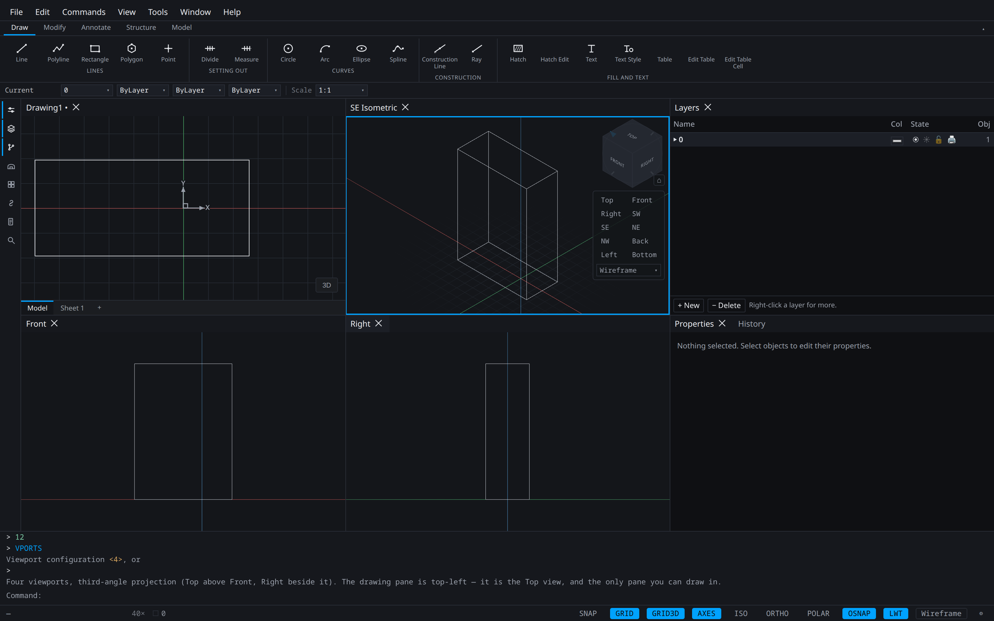
VPORTS gives a four-up arrangement — plan, front, side and isometric — with the active viewport drawn with a border so it is never ambiguous which one a command will affect.
Picking and snapping in three dimensions#
Point picks in the 3D pane resolve as a ray against the current construction plane, so a click means a definite point rather than a direction.
Object snaps work in three dimensions with the same tiers as in 2D, plus Apparent Intersection, which returns where two entities cross in the view but not in space. It is meaningless while everything is coplanar, which is why it belongs here and defaults off.
Ortho in three dimensions locks to UCS X, Y or Z, judged by the axes' screen projections: the axis you are visibly dragging along is the one that wins, and an axis pointing at the camera is not offered.
Visual styles#
A visual style is a named display mode, current per pane and per viewport, and stored on named views and layout viewports.
| Style | Shows |
|---|---|
| 2D wireframe | Edges, no depth cueing |
| 3D wireframe | Edges with the 3D camera |
| Hidden | Edges with hidden lines removed |
| Shaded | Flat-shaded faces under one fixed light |
| Shaded with edges | The same, with edges drawn over |
Shading uses one fixed light. Materials, lights and ray tracing are deliberately out of scope — see the table at the end of this page.
Elevation and thickness#
ELEV sets the current elevation — the Z at which new 2D geometry is created — and the current thickness, which extrudes new 2D geometry into a vertical surface as it is drawn. This is the 2.5D layer, and it covers the simple cases that would otherwise need a solid.
Solids#
A solid is one entity type carrying two things: how it was made, and a mesh to draw.
"How it was made" is either a primitive with parameters — a box's length, width and height — or an operation with inputs: an extrusion of this profile by this height, a union of these two solids. The mesh is derived and can always be thrown away and rebuilt.
That matters for three reasons: editing a profile regenerates the solid that used it, undo needs no bookkeeping of its own because regeneration is a pure function of the inputs, and the same invalidation pass that serves dimensions and hatches serves solids too.
Curvature is faceted. A cylinder is a prism with many sides. The tessellation tolerance is a per-solid property with a drawing-wide default, so a solid can be regenerated finer later without loss as long as its history is intact. The honest consequences:
- A shaded or hidden view shows facet edges on curved surfaces at high zoom.
- Measuring across a tessellated cylinder returns the chord rather than the diameter, short by the sagitta. Object snaps do not have this problem — they resolve against the parametric definition, not the mesh.
Primitives#
Each is parametric: every prompt is a stored parameter, editable afterwards by grip or in the Properties palette. All are created on the construction plane, with height along UCS Z unless a prompt says otherwise.
| Command | Alias | Flow |
|---|---|---|
| BOX | BOX | First corner (or Center) → other corner (or Cube / Length) → height |
| CYLINDER | CYL | Base centre → radius (or Diameter, 3P, 2P, Ttr) → height (or Axis endpoint) |
| CONE | CONE | As CYLINDER, plus a Top radius keyword that makes it a frustum |
| SPHERE | SPHERE | Centre → radius (or Diameter) |
| TORUS | TOR | Centre → overall radius → tube radius |
| WEDGE | WE | As BOX; slopes down along its length from the first corner |
| PYRAMID | PYR | Base centre → Sides (default 4) → base radius → height, with Top radius for a frustum |
Each has a live preview that tracks the cursor. A zero or negative dimension is rejected with a reason — a degenerate solid is not a solid — and typed values use the full unit syntax.
Solids from profiles#
The four ways a 2D drawing becomes a 3D one.
| Command | Alias | Does |
|---|---|---|
| EXTRUDE | EXT | Sweep a closed profile along its normal, a Direction, or a Path, with an optional Taper |
| REVOLVE | REV | Revolve a profile about an axis through an angle |
| SWEEP | SW | Sweep a profile along an arbitrary path |
| LOFT | LOFT | Blend between two or more profiles |
| PRESSPULL | PP | Push or pull a bounded region directly |
The solid stays associative to its profile: editing the profile or the path regenerates the solid. The profile is kept as an editable source, hidden from view and selection and reached through the solid, so that deleting it does not throw away the thing you will want to edit and leaving it visible does not litter every extrusion with a duplicate outline at its base.
Closed profiles only. An open profile would extrude to a surface, and Draft has no surface body — it is refused with that reason rather than silently producing something booleans cannot use. A taper steep enough to close the section before the full height is reached is likewise rejected with the reason.
Booleans#
| Command | Alias |
|---|---|
| UNION | UNI |
| SUBTRACT | SU |
| INTERSECT | IN |
Booleans are mesh operations, and the result keeps its history — the inputs are retained so the operation can be re-evaluated.
Editing solids#
| Command | Alias | Does |
|---|---|---|
| 3DMOVE | 3M | Move along a gizmo axis or plane |
| 3DROTATE | 3R | Rotate about a gizmo axis |
| ALIGN | AL | Align by source and destination point pairs |
| SLICE | SL | Cut a solid with a plane, keeping one or both halves |
| SECTION | SEC | Produce a section region at a plane |
| SOLIDEDIT | SOLIDEDIT | Edit a sub-selected face, edge or vertex |
The 3D pane uses a gizmo rather than grips, because a grip drag cannot express an axis constraint in a projected view without a UCS dance first. Grips remain the 2D mechanism. This is not a compromise between two habits — it is what each mechanism is actually good at.
Generating 2D from 3D#
FLATSHOT (FSHOT) projects the model into the current view as 2D linework — visible edges as one set, hidden edges as another, on layers you choose. That linework is ordinary drawing content: it can be trimmed, dimensioned, hatched and placed on a sheet like anything else.
This is the step the whole chapter exists for.
Files and interoperability#
Meshes exchange as OBJ and STL. 3DS, FBX and glTF carry meshes plus a scene graph and materials; the mesh half is possible and the rest is out of scope. STEP and IGES are B-rep interchange formats, and Draft has no B-rep to write — see below.
What Draft's 3D deliberately does not do#
Each of these is a decision with a reason, not a backlog entry, and each traces to the choice not to hand-write a B-rep or NURBS kernel.
| Not done | Why, and what Draft does instead |
|---|---|
| NURBS surface modelling | A dedicated surface modeller's entire product — a decade of work, and attempting it badly is worse than not attempting it. Draft models with parametric solids and meshes |
| Precise B-rep solids | The same. Curvature is faceted, and the consequences are stated out loud rather than hidden |
| Edge fillets and chamfers on solids | Requires B-rep. The most conspicuous absence, deliberately visible |
| Surface bodies (open, zero-thickness) | No surface representation exists. Thickness covers the simple cases; open profiles are refused with the reason |
| Rendering: materials, lights, ray tracing | A separate product with a separate audience. Shading uses one fixed light; anyone needing an image exports OBJ |
| Walk, fly and camera animation | Visualization, not drafting. Nothing in the workflow above needs them |
| Point clouds and scan data | A large problem in its own right, with its own performance model and no overlap with the rest of the engine |
| STEP / IGES | B-rep interchange formats with no B-rep to write |
| A separate 3D undo stack or entity store | One drawing, one undo stack. Two would disagree, and the disagreement always surfaces at plot time |
The familiarity test applies to this table as much as to the 2D one: a competent user encountering any of these should understand within ten seconds what Draft is and is not — not discover it three weeks into a project.
The parametric node graph#
Deferred past 1.0 on 2026-08-19 and built anyway, shipping 2026-09-01. Both scopes: the drawing's own graph, the editor as a third viewport mode with every gesture routed through a registry command, and component graphs end to end. Eleven graph.* commands; the activity-rail panel has been stage "shipped" since 2026-09-04. This entry read "deferred" with the note "Its panel is listed in the rail, disabled" until 2026-09-10 — by then every clause of that sentence was false.
The node graph is a visual graph that generates drawing geometry from parameters — change a number, and every wall, opening and stair that depends on it moves. It consumes both the 2D and 3D engines, so it cannot be right before they are. Its panel appears in the activity rail, disabled, so the roadmap is visible rather than absent as a mystery.